Flange Plate Clearances
- General Overview
- Tips and Tricks
- Related Tools
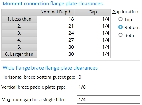
Moment connection flange plate clearances
Column 1: Less than or 2 or 3 or 4 or 5 or Larger than .
' Less than ' appears in the first row of column 1 of the schedule. The first row in this column lets you designate a weld gap for all beams with a nominal depth less than or equal to that listed in the " Nominal Depth " column.
Rows 2 to 5 let you set weld gaps for beams with the exact " Nominal Depth " specified in that row.
' Larger than ' appears in the final row of column 1 of the schedule. The last row in this column lets you designate a weld gap for all beams with a nominal depth greater than or equal to that listed in the " Nominal Depth " column.
Ways to move from cell to cell on the table: Point and click, use Tab and Shift+Tab , use the up/down arrow keys. Backspace can be used to erase characters. For more information, see text entry widgets .
Nominal Depth: The nominal depth of the beam. This applies to beams whose " Section size " is a flanged shape such as wide flange, welded plate wide flange or S shape.
|
| Typically a beam's nominal depth is different from (although close to) the actual depth of the beam. |
Note: Each section size has a " Nominal depth " associated with it in the local shape file . This is the nominal depth that connection design will use for a particular section size.
Gap: The erection clearance between the bolted moment connection flange plate and the beam flange that the plate field bolts to. This gap is, by default, 1/4 inch (6 mm) for each " Nominal Depth ."
Gap location: Top or Bottom or Both .
' Top ' places the " Gap " between the top flange of the beam and the top flange plate.
' Bottom ' applies the " Gap " between the bottom flange of the beam and the bottom flange plate.
' Both ' applies the same " Gap " distance that is entered to both the top and bottom flanges of the beam.
Wide flange brace plate gaps
Horizontal brace bottom gusset gap: The clearance between the wide flange or S shape horizontal brace's bottom gusset and its bottom flange. This applies to wide flange or S shape horizontal braces that do not have a fill plate on their bottom flange. Connection design may decrease the gap that is entered here to prevent the plate from clashing with the supporting beam's bottom flange.
Warning: The maximum " Shop bolt gap " or " Field bolt gap " needs to be as large as the gap that is entered here if you want connection design to be able to insert bolts through the gap.
Vertical brace paddle plate gap: The clearance between the wide flange , S shape or welded plate wide flange vertical brace's top/bottom paddle plate and its top/bottom flange. The distance entered here is applied to each of the two gaps.
Maximum gap for a single filler: A clearance. If the " Gap " in a bolted moment connection with slip critical bolts is greater than this maximum gap, connection design employs in its calculations the assumption that multiple filler plates will be used. These filler plates are not modeled. However, the entry made to this field may change the design slip resistance and consequently the number of bolts designed.
Note: If the " Maximum gap... " is equal to or greater than the "Gap" for a given " Nominal Depth ," connection design will not assume that multiple filler plates are used.


|
|
OK (or the Enter key) closes this screen and applies the settings.
Cancel (or the Esc key) closes this screen without saving any changes.
Reset undoes all changes made to this screen since you first opened it. The screen remains open.
- In the model, filler plates are not modeled.
- This table does not apply to beam-to-beam moment splice flange plates.
- Red or yellow exclamation point icons
 or
or 
- Connection design (gaps are applied during)
- Moment connections (settings on this screen applied to)
- Text entry widgets (moving from cell to cell and within cells)
- Moment connections with bolted flange plates (Connection Guide)
- Wide flange horizontal brace (Connection Guide)
- Web vertical wide flange brace with paddle plates (Connection Guide)

